V-1200HD: How to Set Up the Multi-View Outputs
The V-1200HD has two Multi-View outputs. Multi-View 1 is intended for your sources going through the 422 M/E Processor, and Multi-View 2 is for the 444 M/E processor.
If you look at the diagram in the Video Processor menu, you can see which sources go through the two processors:

Note how SDI inputs 1-10 and HDMI inputs 1-2 go to the 422 M/E. HDMI inputs 3 and 4 go there by default, but if you tap the box with horizontal lines between HDMI 3 and 4 and their scalers, it will redraw the line to go to the 444 M/E, so you can directly utilize those inputs.

In Patch Bay 1 there are 8 buses along the right side of the rectangle, B1-B6, and S1-S2. The S1 and S2 buses allow you to route video from the 422 M/E to the 444 M/E, but you are limited to buses like PGM, PST, AUX, and Composition layers. By default, S1 and S2 are not assigned to a bus.

Routing HDMI inputs 3 and 4 straight to the 444 M/E is required if you want to utilize the 444 M/E's Matrix and 1 M/E modes. You can still assign S1 and S2 to channels on the cross-point.
This guide will primarily get your Multi-View 1 and Multi-View 2 configured.
- Note that XPT stands for Crosspoint.
In the below examples, I’m working in 1080i, with 1 M/E, 4 Keyers, and 2 AUXs:

I setup Multi-View 1 as follows:

| Note how I swapped output 1 and 2, and moved up the SDI inputs starting with 3. You can also put HDMI inputs in those slots. |
With the default patch bay mapping, this patches:
- PGM > B1 > SDI OUT 1
- PVW > B2 > SDI OUT 2

For the Labels, you could rename them as follows:

This labels the top boxes of Multi-View 1 as PVW and PGM, and allows you to easily name the camera and media sources for the inputs.
Multi-View 2 works a bit differently. In 1 M/E and Matrix Modes, it will only show video from XPT 1-4, XPT 2-4, or the 444 Video M/E PGM and PVW:
- Note that these XPTs are separate from the 422 processor and 422 XPT’s

Only 1 M/E and Matrix Modes support the 444 XPT Crosspoint:

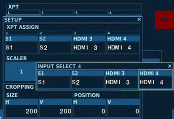
If you tap the [444 VIDEO M/E] button in either of those modes, it opens this menu:

The only options are S1 and S2 (the 422 M/E buses on Patch Bay 1), and HDMI inputs 3 and 4:

Some users may want to try and setup Multi-View 2 as a quad preview for cameras, but it's not recommended. It would require you to route the S1 and S2 patch bay points that tie up AUX buses or Composition layers, and physically split camera feeds into HDMI inputs 3 and 4, or route them from SDI outputs and convert to HDMI. I instead recommend a quad multi-viewer box as a workaround.
If you want to route HDMI inputs 3 and 4 to Multi-View 1, here is a guide. The reason they are separate is they are multi-format inputs primarily intended for the 444 M/E in either Matrix or 1 M/E modes, which is viewed on Multi-View 2.
More Information
For more information about Audio Follows Video, refer to the V-1200HDR/V-1200HD Remote Control Guide.
Note: This is a separate document from the V-1200HD and V-1200HDR Owner's Manual.
